Community Wireless Networks
The key points of a Community ISP (Internet Service Provider) system are:
- The Internet Feed – commonly a leased line
- The Network Services – email and web servers, bandwidth control, controlling access and security.
- Wireless Distribution (this page) – distributing the internet and services to the community.
Wireless Distribution
This page considers the methods available.
Mesh Wireless Networks
These networks consist of individual stations each acting as repeaters where routes between the Internet feed and the end client can be via many routes consisting of many hops.
These systems seem very attractive and are formed by every household acting as a repeater. It can be thought of like a large football net where the places where the string crosses are the clients. This means there are multiple routes between any two points on the net by passing through other points acting as repeaters. If one route fails there will always be another; multiple routes can also be used simultaneously to provide greater bandwidth.
As each repeater has to first listen and then retransmit, the actual bandwidth available is reduced and long delays can occur.
However in practice this does not work in every situation. Although each house can talk to any other that is in wireless range, geography often dictates that there will be a choke point where one side of the net has to pass through a single point to get to the other side. Since the equipment is sold to the customer and is therefore as cheap as possible, it is unlikely to have any protection against power failure or being unplugged or tripped over. Also in this system most users will require external aerials so it can be quite expensive. The typical installed cost for each household is likely to be in the order of £400.

Advantages:
- Easy to extend
- Simple Configuration
- Multiple routes give fault tolerance
- Multiple feed points can allow easy scaling.
Disadvantages:
- Limited real bandwith available because of store and forward system ( a single radio is used to first receive and then retransmit the signal).
- Clients also form the main infrastructure or 'Backbone' so power loss at one point can cause network failure for area of mesh. In rural areas it is quite likely that there will only be one node joining sections of the village which can act as a choke point and single point of failure.
- Because each radio is in a client's house, connected to a normal socket, there is little control over the system.
- Still may require repeaters in rural areas as omni aerials have short range and subject to interference.
- High client install cost.
The technology for Mesh networks is improving all the time and this does offer some very major advantages; however this is more suitable for towns rather than rural areas.
Broadcast Networks
These work by having one central point, normally mounted on a high mast. This can cover a very large area. Whilst this system is therefore simple as there is only the need for only one main transmitter, there are several disadvantages.
The radio band available for such systems is currently not free for long distance links. Special licenses are occasionally granted, however they are likely to be revoked when the band becomes unlicensed. There is currently no equipment available that fully meets the planned specifications from the Radio Communication Agency. Finally the customer premises equipment (CPE) is likely to be very expensive and will require external aerials to be fitted as the radio band used does not pass easily through walls. In the future, when the cost of equipment falls, this method of radio internet distribution will probably offer the best solution.
802.11b/g Networks
The system uses well established low cost technology, but can be quite difficult to implement successfully.
Network Topology
One central point is chosen which acts as an 'access point' for users to connect to and also acts as a feeder to repeater stations which receive the signal and then act as access points for other clients. Using this system, large areas are covered by using multiple repeater points.
With such a system, it is important to separate the links from the main site to the repeaters from the channels serving the users so that one bad user does not damage the main links (commonly called the backbone).
There are two basic components that make up such systems:
The Access Point
This is a radio unit that can communicate wirelessly with up to 32 individual users.
The Bridge
This is a radio unit that can communicate only with one (called a point to point link) or more (called a point to multi-point link) other bridges. It does not connect to clients.
So a typical design to cover an area might look like

More repeaters can be added as required and it is possible to hop from one repeater to another.

There are some shortcuts that some suppliers may make, however they should be avoided at all costs.

The first shortcut is to connect the bridge directly to an access point. This is not a good idea as the feed to the next repeater only has as much throughput as one of the other clients.
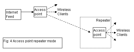
The second shortcut is to use a special mode that some access points support called 'repeater mode'. Whilst this can offer a very low cost solution it has a major problem.
Radio links are 'half duplex' which means that they can only transmit data in one direction at a time. So when acting in repeater mode, they first have to listen to the signal coming in and then retransmit it. Accordingly the maximum speed that data can pass through is halved. Comparing Fig 1 with Fig 4 shows that a lot less equipment is required, however the system will be too slow for broadband use.
After four radio links, the delays introduced can degrade the performance of the network and so no more that two or three stages of repeaters should be used.
Short Range Wireless Network Repeaters

In this design there is one central station which feeds multiple repeater stations. Each repeater station feeds one or more repeater stations and local clients. Repeater range is typically 600m.
Advantages:
- Cheap client install as internal aerials can be used.
- Good coverage for built up areas.
- Simple site surveys.
- Cheap.
Disadvantages:
- Lots of repeaters required to cover wide areas such as rural locations.
- Multiple hops between repeaters contributes to poor performance.
- Often the main feed (backbone) is shared with client access and therefore can be unreliable.
- Indoor aerials subject to being moved.
- Poor packet loss.
- Large number of repeaters required means higher cost.
Long Range Repeaters
Similar in principle to the short range repeaters above, except the repeaters are more widely spaced. Typical repeater coverage is 1km.

Advantages:
- Fewer repeaters required so higher quality equipment can be used, typically uninterruptible power supplies are used to protect repeaters against local power failure.
- Repeater stations separate the 'backbone' connectivity from the clients using different channels to improve reliability.
- External aerials give better signal quality to end clients.
Disadvantages:
- More complex to design as has to be closely matched to geography.
- Careful channel planning and good site surveys required for successful implementation.
- Client installs typically £100 more than short range systems.
- External aerials on clients properties means computers cannot be easily moved around the clients house.
- Not suitable for high density population areas such as towns.
Whilst Navigator can supply systems based on any of the above methods, we recommend the long range repeater system system for rural areas as in our experience it will give the best quality internet provision and the most reliable system. The costs are broadly similar between all three options, however for densely populated areas options 1 and 2 are the most cost effective.
The Clients Equipment
This is often called CPE or Customer Premises Equipment. There are three main options here, each with its own advantages or disadvantages
| PCI Card | USB Client | Ethernet Client |
|---|---|---|
| – requires opening and mounting a card in the customers PC. Not suitable for self install. Possible conflicts with users PC | + plugs into most modern computers via existing USB socket | – computer must have network card fitted (many haven't), therefore may require opening customers PC and supply of network card. |
| – supplied aerial is mounted by computer so an external aerial is nearly always required | + can be moved away from computer for best reception | + can be moved away from computer for best reception |
| + cheap (~£45) | + cheap(~£50) | – not cheap (~£100) |
| + built in aerial connector | – needs modifying to take external aerial connector | + built in aerial connector |
| + no external power supply required | + no external power supply required | – external power supply required |
Since radio waves used by 802.11b (a frequency of 2.4GHz) do not pass through buildings, external aerials are needed: when the PC is on the wrong side of the house from the access point; there is no direct line of sight between the client's equipment and the access point due to hills and other buildings; or lastly when a greater range is required.
Unfortunately the most commonly required piece of equipment is very hard to find: namely a USB client with an external aerial connector. It is likely that in any system a combination of USB and Ethernet clients will be required.
Alternatives to Radio Links
There will always be cases where a radio link won't work due to the distance being too large or there being hills or other obstacles in the way.
A common solution is to use Baseband (called EPS9 by BT) circuits to link using copper wires between two points on the same telephone exchange.
Basically these comprise of a pair of copper wires from one end of the link to the telephone exchange and then on to the other end of the link. These circuits cost approximately £800 to install, the £400 per year line rental. At each end of the link a DSL (Digital Subscriber Line) router is used to convert between the telephone lines and the network. DSL routers typically cost about £500 each.
The speed that can be achieved on the link depends on the distance traveled, the quality of the lines and the quality of the routers used. Typically the maximum distance that can be used with this method is 4Km for a 2Mbs link.
To link between two points on different exchanges BT offer several services, such as 'megastream'. This is charged for two ends and then for the distance traveled between the two exchanges. The likely costs are around £8,000 install and then £4,000 per year for the line rental. If this is required it is often cheaper to buy two leased lines from an ISP of smaller capacity instead of one large leased line and then trying to transfer it over a megastream link.
Another method for linking across exchanges is to use a baseband link from one end of the link to a suitable property on the edge of the exchange area and then cross the remaining distance using a radio link.
Navigator are experienced in the design and implementation of large scale wireless systems, and working with our partner companies can offer a complete solution for a community system.

No comments:
Post a Comment