Computer And Technologies

Computer And Technologies: 04/09

Thursday 23 April 2009

Debian Packages (Ubuntu Linux)


#!/bin/bash
clear
# it will install all important packages.
sudo apt-get install xawtv-tools
sudo apt-get install recordmydesktop
sudo apt-get install manpages-dev
sudo apt-get install cvs
sudo apt-get install ssh
sudo apt-get install openvpn
#sudo apt-get install sox
sudo apt-get install vim
sudo apt-get install vim-common
sudo apt-get install vim-gnome
sudo apt-get install vim-gui-common
sudo apt-get install vim-runtime
sudo apt-get install vim-scripts
sudo apt-get install vim-tiny
sudo apt-get install wmctrl
sudo apt-get install cscope
sudo apt-get update
sudo apt-get install vlc vlc-plugin-esd mozilla-plugin-vlc
sudo apt-get install vim-runtime
sudo apt-get install vim-scripts
sudo apt-get install vim-tiny
sudo apt-get install build-essential
sudo apt-get install mplayer-nogui
sudo apt-get install mplayer
sudo apt-get install manpages-dev
sudo apt-get install stl-manual
sudo apt-get install autoconf
sudo apt-get install mtd-tool
sudo apt-get install lynx-cur-wrapper
sudo apt-get install lynx
sudo apt-get install lynx-cur
sudo apt-get install doxygen
sudo apt-get install bison
sudo apt-get install flex
sudo apt-get install xxgdb

For More information Use this link:-
"http://www.debian-multimedia.org/dists/testing/main/binary-i386/"

Systems Development Life Cycle (SDLC)

Systems Development Life Cycle


Management and control


Wireless Local Area Network Standards

The main methods of operation for wireless lans are as follows:

Ad Hoc this is where individual PCs link to each other on an informal basis, so that if there are 5 PCs they will all talk to each other directly as required. In reality this type of system should be avoided at all costs; it is problematic and difficult to set up to provide a reliable service.

Infrastructure Mode This is where each PC talks to a central station, normally called an access point. The messages from one PC are passed to the access point then onto the wired network that the access point is connected to or relayed to another PC wirelessly if required. This system is better to use as it is easier to manage and set up as each client PC only talks to (normally) one access point.

Bridging This is where effectively two specialised access points talk directly to each other to form a 'bridge' between two networks. Some access points can be configured to act as bridges — but it should be noted that the communication system then tends to become non standard so only equipment from the same manufacturer will talk to each other.

These links tend to be classed as point to point links where one bridge talks to another, however point to multipoint bridging can be used (sometimes called Wireless Distribution) to allow one central bridge to talk to several bridges. This is useful where a large area needs to be covered, as each of the remote bridges can then be connected to an access point to allow an area of several square miles to be covered or to work round obstacles.

A fourth mode is available on some hardware called Repeater Mode — this is where the equipment can receive signals from one bridge and relay it to another bridge or to end clients directly. This is useful for working round obstacles or for longer ranges, however as it listens and then repeats, it tends to have a working bandwidth of less than half that of a normal bridge — Buffalo equipment for instance when working in repeater mode has a maximum throughput of 1.2mb/s.

License-Free Wireless Lans

There are three commonly used systems:

802.11b

  • Based on 2.4GHz
  • 13 channels in the UK
  • Three non-overlapping channels
  • Typical throughput 3 to 5Mb/s
  • Well established and low cost
  • Good range
  • Suffers interference from microwave ovens, some portable phones and video senders
  • Suitable for use throughout Europe (7dBm power limit in France)

802.11g

  • Based on 2.4GHz
  • Backwards compatible with 802.11b
  • Three non-overlapping channels
  • Typical throughput 6 to 20Mb/s but performance falls off very rapidly with range.
  • Same interference problems as 802.11b
  • Similar throughput at longer ranges as 802.11b
  • Suitable for use throughout Europe (7dBm power limit in France)

802.11a

  • Based on 5GHz
  • 12 non-overlapping channels
  • Typical throughput 6 to 28Mb/s
  • Limited range in outdoor environments, but similar ranges for indoor environments.
  • Expensive aerials and cable required and requires great care in installing for longer range links.
  • Much reduced interference problems
  • Best suited for areas where there is a high density of radio lans.
  • Signals are absorbed much more than at 2.4GHz so it is less suitable for penetrating through anything than partition walls. This can be overcome by using more access points.
  • Performance very variable between manufacturers.
  • Not yet legal in many European countries.

Power Levels

In Europe at 2.4GHz we are limited by ETSI regulations to 20dbmW.

That is 20dB gain above 1mW or 100mW Effective radiated power compared to an isotropic (0 gain) aerial. This figure includes the gain from the aerial and losses from cabling.

So to calculate the EIRP of your system:
EIRP=Output power of card or access point in dBm – cable loss in dB – connector losses in dB + aerial gain in dBi

A typical card gives out +15dBmW so the largest aerial allowed is +5dB. However on a typical installation an +8dB aerial can be used as there is quite often a 3dB loss on the aerial cable.

The exception to the above is France, where the maximum output power is limited to 7dBm (5mW EIRP) at 2.4GHz.

For 802.11a the 5.2-5.8GHz band is not available in all European countries.

See the Calculators & Tools page for a dBm to mW converter.

DTI Regulations

If more than 20 properties are connected to a wireless lan, a telecomms operator license may be required. However if fewer than this number of properties are being linked the 'self provision' license can be used — which does not have to be applied for.

Receiver Sensitivity

Receiver sensitivity is a very important figure for wireless lan equipment. It indicates how low a signal can be before it cannot be used. This ranges between -85dB and -78dB according to manufacturer.

The best figure is the largest -ve number i.e. -85dB is better than -78dB — this corresponds to a difference of 7dB in available signal and in clear interference free conditions corresponds to a range improvement of over 4x.

This is less important in areas with interference as the limit of reception is set by the signal to noise ratio rather than the sensitivity of the receiver.

SSID

This stands for ServiceSet IDentifier. It is a code that identifies the radio network.

No wireless client can access the network unless they have the SSID code. Although it is possible to hide the SSID, it is not good practice to do so, as it can cause difficulties in communication and makes it hard to track down sources of interference. The SSID identifies one or more interconnected radio groups called Basic Service sets.

WEP and Security

WEP stands for Wired Equivalency Privacy. It is a form of encryption that was intended to provide the same level of security as that found on a normal wired LAN.

It is available in several strengths 64,128 and 256 bit encryption. The higher the number the better the encryption. The encryption is accomplished by having a set of WEP keys (or codes) that are entered on both end of the link. Only stations that have the correct WEP key can decode the data.

In reality however, WEP has two problems. Firstly there are certain keys that are weaker than others so can be broken more easily. Some manufacturers have implemented what is called weak IV filtering which reduces the risks of using a weak key, however this has been implemented with only varying degrees of success.

Whilst theoretically 128bit encryption would take a supercomputer and months to crack, in reality some of the messmessages being passed have known content and so the encrypted and unencrypted information can be compared. This makes it a lot easier to crack the encryption and work out the keys. Programs are readily available that if allowed to eavesdrop on a network for many hours can provide the hacker with the WEP keys.

Some manufacturers support 802.1x authentication systems which improve the security somewhat, others use proprietary systems that change the keys automatically at intervals. Most now also support mac address filtering (see below) and hiding the SSID. One of the most effective ways of securing the system is to make sure it doesn't cover any areas that you don't need it to. Other techniques like VPN can also be used to secure a wireless link.

The overall answer is that 802.11 as a system can be made secure enough for general purpose use, but it is not secure enough for use where the information stored has a high value to outsiders. It is certainly not suitable for banking or defence systems.

WPA and WPA-PSK

WPA stands for Wifi Protected Access. This system was introduced to overcome the limitations of WEP.

It is available in two forms, WPA-PSK (Pre Shared Key) which is used in smaller networks and like WEP involves entering a set of keys on each piece of equipment. However the system changes the codes and makes it much harder to break into the system.

WPA is a more advanced system that is suitable for use in larger systems and relies on authenticating each user against a RADIUS server. This is significantly more secure however can be expensive and complex to implement.

MAC Addresses and MAC Filtering / Authorisation

This is short for Media Access Control address; it is a a unique identifier for every networking interface.

Every piece of network equipment that uses the basic 802 ethernet standard such as TCP (transmission control protocol) has built into its hardware a unique mac address which is sent with the packets of data. This can be used to identify the piece of equipment.

Access points support MAC address filtering or authentication which means that they can be configured to either blacklist certain MAC addresses or only allow known MAC addresses to connect. This is a simple method of stopping people connecting to your system. It is not infallible as it is possible to 'spoof' or fake the MAC address, and utilities to achieve this are freely avilable on the internet.

Currently, it is a 48-bit string made up of a 24-bit Organizationally Unique Identifier (OUI or company_id; see http://standards.ieee.org/faqs/OUI.html) that identifies the vendor of a product and a 24-bit string that is assigned by that vendor to provide a unique address.

The Hidden-Node Problem

The 802.11 system uses Carrier Sense Multiple Access/Collision Avoidance (CSMA/CA). Basically, it allows the transmitting station to request airtime by sending a Request To Send (RTS) frame. This frame contains the time at which it needs the medium. The AP will respond to the RTS with a Clear To Send (CTS) frame. This frame indicates the time when it will allow the station to use the medium. All stations associated with the AP will see the CTS frame. As a result, they will know not to transmit for that period of time.

By using packet fragmentation/defragmentation along with the RTS/CTS hand-shake mechanism, it is possible to optimize throughput by minimizing the potential for errors. In theory at least…

Community Wireless Networks!!

Community Wireless Networks

The key points of a Community ISP (Internet Service Provider) system are:

  • The Internet Feed – commonly a leased line
  • The Network Services – email and web servers, bandwidth control, controlling access and security.
  • Wireless Distribution (this page) – distributing the internet and services to the community.

Wireless Distribution

This page considers the methods available.

Mesh Wireless Networks

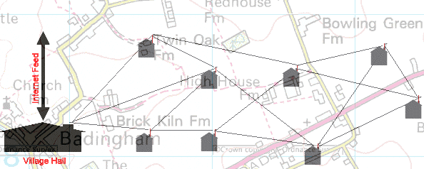
These networks consist of individual stations each acting as repeaters where routes between the Internet feed and the end client can be via many routes consisting of many hops.

These systems seem very attractive and are formed by every household acting as a repeater. It can be thought of like a large football net where the places where the string crosses are the clients. This means there are multiple routes between any two points on the net by passing through other points acting as repeaters. If one route fails there will always be another; multiple routes can also be used simultaneously to provide greater bandwidth.

As each repeater has to first listen and then retransmit, the actual bandwidth available is reduced and long delays can occur.

However in practice this does not work in every situation. Although each house can talk to any other that is in wireless range, geography often dictates that there will be a choke point where one side of the net has to pass through a single point to get to the other side. Since the equipment is sold to the customer and is therefore as cheap as possible, it is unlikely to have any protection against power failure or being unplugged or tripped over. Also in this system most users will require external aerials so it can be quite expensive. The typical installed cost for each household is likely to be in the order of £400.

example of a mesh layout superimposed on a map

Advantages:

  • Easy to extend
  • Simple Configuration
  • Multiple routes give fault tolerance
  • Multiple feed points can allow easy scaling.

Disadvantages:

  • Limited real bandwith available because of store and forward system ( a single radio is used to first receive and then retransmit the signal).
  • Clients also form the main infrastructure or 'Backbone' so power loss at one point can cause network failure for area of mesh. In rural areas it is quite likely that there will only be one node joining sections of the village which can act as a choke point and single point of failure.
  • Because each radio is in a client's house, connected to a normal socket, there is little control over the system.
  • Still may require repeaters in rural areas as omni aerials have short range and subject to interference.
  • High client install cost.

The technology for Mesh networks is improving all the time and this does offer some very major advantages; however this is more suitable for towns rather than rural areas.

Broadcast Networks

These work by having one central point, normally mounted on a high mast. This can cover a very large area. Whilst this system is therefore simple as there is only the need for only one main transmitter, there are several disadvantages.

The radio band available for such systems is currently not free for long distance links. Special licenses are occasionally granted, however they are likely to be revoked when the band becomes unlicensed. There is currently no equipment available that fully meets the planned specifications from the Radio Communication Agency. Finally the customer premises equipment (CPE) is likely to be very expensive and will require external aerials to be fitted as the radio band used does not pass easily through walls. In the future, when the cost of equipment falls, this method of radio internet distribution will probably offer the best solution.

802.11b/g Networks

The system uses well established low cost technology, but can be quite difficult to implement successfully.

Network Topology

One central point is chosen which acts as an 'access point' for users to connect to and also acts as a feeder to repeater stations which receive the signal and then act as access points for other clients. Using this system, large areas are covered by using multiple repeater points.

With such a system, it is important to separate the links from the main site to the repeaters from the channels serving the users so that one bad user does not damage the main links (commonly called the backbone).

There are two basic components that make up such systems:

The Access Point

This is a radio unit that can communicate wirelessly with up to 32 individual users.

The Bridge

This is a radio unit that can communicate only with one (called a point to point link) or more (called a point to multi-point link) other bridges. It does not connect to clients.

So a typical design to cover an area might look like

More repeaters can be added as required and it is possible to hop from one repeater to another.

There are some shortcuts that some suppliers may make, however they should be avoided at all costs.

The first shortcut is to connect the bridge directly to an access point. This is not a good idea as the feed to the next repeater only has as much throughput as one of the other clients.

The second shortcut is to use a special mode that some access points support called 'repeater mode'. Whilst this can offer a very low cost solution it has a major problem.

Radio links are 'half duplex' which means that they can only transmit data in one direction at a time. So when acting in repeater mode, they first have to listen to the signal coming in and then retransmit it. Accordingly the maximum speed that data can pass through is halved. Comparing Fig 1 with Fig 4 shows that a lot less equipment is required, however the system will be too slow for broadband use.

After four radio links, the delays introduced can degrade the performance of the network and so no more that two or three stages of repeaters should be used.

Short Range Wireless Network Repeaters

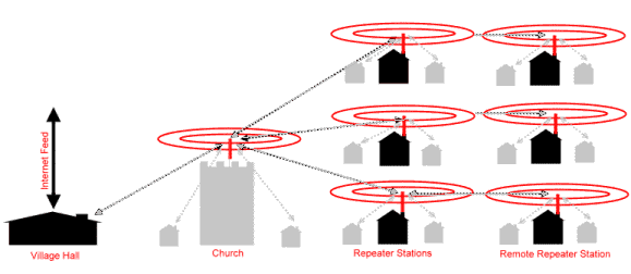
diagrammatic example of a network using short range wireless repeaters

In this design there is one central station which feeds multiple repeater stations. Each repeater station feeds one or more repeater stations and local clients. Repeater range is typically 600m.

Advantages:

  • Cheap client install as internal aerials can be used.
  • Good coverage for built up areas.
  • Simple site surveys.
  • Cheap.

Disadvantages:

  • Lots of repeaters required to cover wide areas such as rural locations.
  • Multiple hops between repeaters contributes to poor performance.
  • Often the main feed (backbone) is shared with client access and therefore can be unreliable.
  • Indoor aerials subject to being moved.
  • Poor packet loss.
  • Large number of repeaters required means higher cost.

Long Range Repeaters

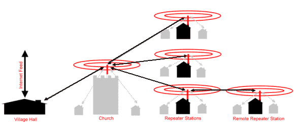
Similar in principle to the short range repeaters above, except the repeaters are more widely spaced. Typical repeater coverage is 1km.

diagrammatic example of a network using long range wireless repeaters

Advantages:

  • Fewer repeaters required so higher quality equipment can be used, typically uninterruptible power supplies are used to protect repeaters against local power failure.
  • Repeater stations separate the 'backbone' connectivity from the clients using different channels to improve reliability.
  • External aerials give better signal quality to end clients.

Disadvantages:

  • More complex to design as has to be closely matched to geography.
  • Careful channel planning and good site surveys required for successful implementation.
  • Client installs typically £100 more than short range systems.
  • External aerials on clients properties means computers cannot be easily moved around the clients house.
  • Not suitable for high density population areas such as towns.

Whilst Navigator can supply systems based on any of the above methods, we recommend the long range repeater system system for rural areas as in our experience it will give the best quality internet provision and the most reliable system. The costs are broadly similar between all three options, however for densely populated areas options 1 and 2 are the most cost effective.

The Clients Equipment

This is often called CPE or Customer Premises Equipment. There are three main options here, each with its own advantages or disadvantages

PCI CardUSB ClientEthernet Client
– requires opening and mounting a card in the customers PC. Not suitable for self install. Possible conflicts with users PC + plugs into most modern computers via existing USB socket – computer must have network card fitted (many haven't), therefore may require opening customers PC and supply of network card.
– supplied aerial is mounted by computer so an external aerial is nearly always required + can be moved away from computer for best reception + can be moved away from computer for best reception
+ cheap (~£45) + cheap(~£50) – not cheap (~£100)
+ built in aerial connector – needs modifying to take external aerial connector + built in aerial connector
+ no external power supply required + no external power supply required – external power supply required

Since radio waves used by 802.11b (a frequency of 2.4GHz) do not pass through buildings, external aerials are needed: when the PC is on the wrong side of the house from the access point; there is no direct line of sight between the client's equipment and the access point due to hills and other buildings; or lastly when a greater range is required.

Unfortunately the most commonly required piece of equipment is very hard to find: namely a USB client with an external aerial connector. It is likely that in any system a combination of USB and Ethernet clients will be required.

Alternatives to Radio Links

There will always be cases where a radio link won't work due to the distance being too large or there being hills or other obstacles in the way.

A common solution is to use Baseband (called EPS9 by BT) circuits to link using copper wires between two points on the same telephone exchange.

Basically these comprise of a pair of copper wires from one end of the link to the telephone exchange and then on to the other end of the link. These circuits cost approximately £800 to install, the £400 per year line rental. At each end of the link a DSL (Digital Subscriber Line) router is used to convert between the telephone lines and the network. DSL routers typically cost about £500 each.

The speed that can be achieved on the link depends on the distance traveled, the quality of the lines and the quality of the routers used. Typically the maximum distance that can be used with this method is 4Km for a 2Mbs link.

To link between two points on different exchanges BT offer several services, such as 'megastream'. This is charged for two ends and then for the distance traveled between the two exchanges. The likely costs are around £8,000 install and then £4,000 per year for the line rental. If this is required it is often cheaper to buy two leased lines from an ISP of smaller capacity instead of one large leased line and then trying to transfer it over a megastream link.

Another method for linking across exchanges is to use a baseband link from one end of the link to a suitable property on the edge of the exchange area and then cross the remaining distance using a radio link.

Navigator are experienced in the design and implementation of large scale wireless systems, and working with our partner companies can offer a complete solution for a community system.

The difference between Repeater and Relay Station..

The Relay Station nearly has all the functionality of a base station. In the following part, I will make some comparison between the Relay Station and the Repeater.

The advantages of using Repeater:

  1. With the same coverage area, the investment of repeater is much lower.
  2. The shape of coverage is more flexible. Normally a base station has circle coverage, while multiple repeaters can make multiple coverage shapes, such as "--", "L", "N" and "M".
  3. In the beginning of forming the network, because the number of users is small and the benefit of investment is low, some repeaters can be used instead of base stations. When the users expand, they can be changed into base stations. And the replaced repeaters can be used in further places.
  4. Because the building and transmission circuit are not needed, the network can be rapidly established.
The disadvantages of Repeater:
  1. It cannot increase system capacity.
  2. After the introduction of repeater, it will increase more than 3dB noise to base station. It makes the working environment of base station worse and decreases its coverage. So in a sector of one base station, the maximum of two repeaters can be used.
  3. Repeater can only use frequency division, but not code division. One repeater usually amplifies the signal of multiple base stations and multiple sectors. If there are a lot of repeaters, it makes mess in base station phases and pilots. The improvement is hard and it increses a lot of unnecessary soft handovers.
  4. The network management functionality and device detection is far from relay station. If there is something wrong with the repeater, it is not easily to be conscious.
  5. Because of the limitation of separation requirement, the installation environment for a repeater is much more critical than a relay station. This makes its function not be sufficiently performed.
  6. If there is interferencing source around the repeater, it will make severe influence on the original network. If the repeater antenna is high, it will effect larger area. CDMA is a co-frequency system, maybe all the base stations around it will be destroyed by congestion.

From some statistical results, in China, the installation ratio between repeaters and base stations is as high as or higher than 2:1. And because the people density of the country is quite high, the installation ratio should not be too large. If there is no fiber repeater, only for radio coupling outdoor repeater, this ratio should not be larger than 1. When it is the time for system plan, the repeaters work as transition devices for continuous development. The repeaters installed for long term use should be further decreased. In large or middle sized cities or high density areas, radio coupling outdoor repeaters should not be used.

On the other hand, because in CDMA system the frequency reuse is 1. So usage of the repeaters in CDMA system and the ones in GSM systems has difference. The use of repeaters has relation with the whole system performance. While in GSM sytem the use of repeaters only has relation with several corresponding channel performance. Therefore, proper plan of repeater network, strict project survey and implementation have much importance in improving CDMA network performance.

What is Relay Station (RS)?


Definition in Wikipedia:
Generally, an intermediate station that passes information between terminals or other relay stations.

Definition in IEEE802.16j Terminology:
Mobile Multihop Relay (MMR): The concept of relaying user data and possibly control information between an MMR base station and an IEEE Standard 802.16 compliant mobile station through one or more relay stations.

Informative Notes: Licensed spectrum is used for relay. The purpose of enabling relay is to enhance coverage, range, throughput, and capacity of an MMR–BS, and to enable very low power devices to participate in the network. The adjective “mobile” used here refers to the fact that both mobile subscriber stations and mobile relay stations are supported. It may be possible to establish multiple communication paths between an MMR-BS and a MS and communicate the same user data and/or control information through both paths to improve performance.

What is Repeater?


Nowadays the mobile communication is developing very repidly. No matter what kind of communication coverage, there may be weak signal and blind areas. While in some far away areas and blind areas with very few users, the cost of building analog or digital base station is very high and the basic installation is also quite complicated. Therefore it is necessary to provide a device with low cost, easy installation, but with the functionality of base station--Repeater. So mobile communication service providers start setting repeaters in radio blind areas such as inside the buildings, basement, etc., to satisfy the service requirements of users to the maximum extent.

In the beginning of formation of repeater market in China, radio device and FM broadcast repeaters were used. Since the later part of 90s', as the mobile phones were more and more popular, repeater market has been developed continuously. Repeater can enlarge the coverage of already built analog and digital base station and it is an efficient and unexpensive method to solve blind and remote area problems.

  • Repeater definition

A repeater is an electronic device that receives a weak or low-level signal and retransmits it at a higher level or higher power with the same frequency, so that the signal can cover longer distances without degradation. To use repeater as "small capacity, large coverage" method is mainly because that with the condition of not increasing the number of base stations to ensure network cover and its cost is much lower than cell system with the same effect.

Compared with base station, it has the advantages of simpler architecture, lower cost an easier installation. It can be used in many blind and weak areas, such as shopping mall, hotel, airport, port, station, subway, tunnel, highway, island, etc., to improve communication quality.

  • Repeater types:
  1. · GSM mobile communication repeater ·
  2. CDMA mobile communication repeater ·
  3. GSM/CDMA fiber repeater
  • Repeater applications:

-Urban area with high density: because of the large number of users and base stations, normally the large signal blind area problem does exit. Repeater is usually used to cover blind areas and the areas inside the building. Wireless repeaters are often used. With the increase of the number of buildings, the number of required repeaters increases. Then the situation of one base station with multiple repeaters appears. However, the introduction of repeater will definitely cause the interference to base station. And the interference will increase with the increase of the number of repeaters. Especially when large power repeater is introduced, the system interference is much more severe. Therefore low power repeater (less than 1W) should be applied.

-Edge of city: in the beginning of CDMA network establishment, because the small number of base stations, large power wireless or fiber repeaters are used. It is mainly to solve coverage problem. In the areas with fibers, it is better to use fiber repeater with 10W output power. When there is no fiber resource, wireless repeater with 5W/10W is used to extend coverage, which equals to a base station output.

-Suburban and village: it is also to solve coverage problem. In the areas with fiber, it is better to use large power fiber repeater (10W/20W) to enlarge coverage. In the areas where there is no fiber resource but can receive signal from base station, wireless repeater can be used to solve coverage problem. And frequency shift repeater can be utilized to increase coverage distance.

The difference between Repeater and Relay Station..

The Relay Station nearly has all the functionality of a base station. In the following part, I will make some comparison between the Relay Station and the Repeater.

The advantages of using Repeater:

  1. With the same coverage area, the investment of repeater is much lower.
  2. The shape of coverage is more flexible. Normally a base station has circle coverage, while multiple repeaters can make multiple coverage shapes, such as "--", "L", "N" and "M".
  3. In the beginning of forming the network, because the number of users is small and the benefit of investment is low, some repeaters can be used instead of base stations. When the users expand, they can be changed into base stations. And the replaced repeaters can be used in further places.
  4. Because the building and transmission circuit are not needed, the network can be rapidly established.
The disadvantages of Repeater:
  1. It cannot increase system capacity.
  2. After the introduction of repeater, it will increase more than 3dB noise to base station. It makes the working environment of base station worse and decreases its coverage. So in a sector of one base station, the maximum of two repeaters can be used.
  3. Repeater can only use frequency division, but not code division. One repeater usually amplifies the signal of multiple base stations and multiple sectors. If there are a lot of repeaters, it makes mess in base station phases and pilots. The improvement is hard and it increses a lot of unnecessary soft handovers.
  4. The network management functionality and device detection is far from relay station. If there is something wrong with the repeater, it is not easily to be conscious.
  5. Because of the limitation of separation requirement, the installation environment for a repeater is much more critical than a relay station. This makes its function not be sufficiently performed.
  6. If there is interferencing source around the repeater, it will make severe influence on the original network. If the repeater antenna is high, it will effect larger area. CDMA is a co-frequency system, maybe all the base stations around it will be destroyed by congestion.

From some statistical results, in China, the installation ratio between repeaters and base stations is as high as or higher than 2:1. And because the people density of the country is quite high, the installation ratio should not be too large. If there is no fiber repeater, only for radio coupling outdoor repeater, this ratio should not be larger than 1. When it is the time for system plan, the repeaters work as transition devices for continuous development. The repeaters installed for long term use should be further decreased. In large or middle sized cities or high density areas, radio coupling outdoor repeaters should not be used.

On the other hand, because in CDMA system the frequency reuse is 1. So usage of the repeaters in CDMA system and the ones in GSM systems has difference. The use of repeaters has relation with the whole system performance. While in GSM sytem the use of repeaters only has relation with several corresponding channel performance. Therefore, proper plan of repeater network, strict project survey and implementation have much importance in improving CDMA network performance.

Why to develop IEEE802.16j?

Currently in the point-to-multipoint architecture, wireless communication easily has some hidden places. And the far away users' transmission speed decreases because of the drop of RSSI (Received Signal Strength Indication). IEEE 802.16 standard session started setting up Relay Task Group since the May of 2006 making the standard for supporting mobile user's multi-hop relay technology. The standard is designed to provide the signal relay between base station and mobile station to achieve the purposes of throughput enhancement and coverage extension. The IEEE802.16j is developed based on IEEE802.16e as its amendment.

  • Scope

It specifies OFDMA physical layer and medium access control layer enhancements to IEEE Std 802.16 for licensed bands to enable the operation of relay stations. Subscriber station specifications are not changed.

  • Purpose

The purpose of this amendment is to enhance coverage, throughput and system capacity of 802.16 networks by specifying 802.16 multihop relay capabilities and functionalities of interoperable relay stations and base stations.

  • Reason

The multihop relay is a promising solution to expand coverage and to enhance throughput and system capacity for IEEE 802.16 system. It is expected that the complexity of relay stations will be considerably less than the complexity of legacy IEEE802.16 base station. The gains in coverage and throughput can be leveraged to reduce total deployment cost for a given system performance requirement and thereby improve the economic viability of IEEE802.16 systems. Relay functionality enables repid deployment and reduces the cost of system operation. These advantages will expand the market opportunity for broadband wireless access. This project aims to enable exploitation of such advantages by adding appropriate relay functionality to IEEE Std. 802.16 through the proposed amendment. Stakeholders include manufactures and operators of IEEE 802.16 networks.

WiMAX Forum and IEEE 802.16..

One of the main objectives of the WiMAX Forum is to create a single interoperable standard from the IEEE 802.16 and ETSI HiperMAN standards. This is achieved by the creation of System Profiles. Based upon what the WiMAX Forum sees in terms of service provider and vendor equipment plans, the WiMAX Forum has decided to focus first on profiles for the 256 OFDM PHY mode of the 802.16-2004 standard, which was ratified by the IEEE in June 2004. This physical layer (PHY) will be combined with a single media access controller (MAC), ensuring a uniform base for all WiMAX implementations.
Compliance with the 802.16 standard does not mean equipment is WiMAX Forum Certified™ or that it is interoperable with other vendors’ equipment. However, if a piece of equipment has earned the WiMAX Forum Certified™ designation, it is both compliant with the 802.16 standard and interoperable with other vendors’ equipment that is also WiMAX Forum Certified™.

IEEE 802.16a standardization focused on fixed broadband access. IEEE 802.16-2004 enhanced the standard by providing support for indoor CPE. The IEEE 802.16e standard is an extension to the approved IEEE 802.16-2004 standard. The purpose of 802.16e (also known as IEEE 802.16e-2005) is to add data mobility to the current standard, which is designed mainly for fixed operation.

IEEE approved the initial 802.16 standard for wireless MAN for the 10-66 GHz frequency range in December 2001. The 802.16a extension for sub-11 GHz was approved in January 2003. The 802.16-2004 standard was ratified by the IEEE in June 2004. The 802.16e-2005 standard was approved in December 2005.

The structure and process of WiMAX Forum certification is most like that of Wi-Fi Alliance, except that Wi-Fi Alliance only tests products for interoperability, whereas WiMAX Forum tests for both conformance to the technical standard and device interoperability. Testing conformance to the standard means that products just don’t work with each other out of luck, rather they are designed in a manner that allows them to implement the protocols in exactly the same way. This ensures that over time the products can be enhanced or new models can be issued with a higher likelihood of deployment in a common network.

Wednesday 22 April 2009

What is WiMAX?


WiMAX (World Interoperability for Microwave Access), is a standards-based technology enabling the delivery of last mile wireless broadband access as an alternative to cable and DSL. WiMAX will provide fixed, nomadic, portable and mobile wireless broadband connectivity without the need for direct line-of-sight with a base station. In a typical cell radius deployment of 3 to 10 kilometers, WiMAX Forum Certified systems can be expected to deliver capacity of up to 40 Mbps per channel, for fixed and portable access applications. This is enough bandwidth to simultaneously support hundreds of businesses with T-1 speed connectivity and thousands of residences with DSL speed connectivity. Mobile network deployments are expected to provide up to 15 Mbps of capacity within a typical cell radius deployment of up to three kilometers. WiMAX technology already has been incorporated in notebook computers and PDAs, allowing for urban areas and cities to become “MetroZones” for portable outdoor broadband wireless access.
There are two main applications of WiMAX today:
Fixed WiMAX (IEEE802.16-2004) applications are point-to-multipoint enabling broadband access to homes and businesses, whereas mobile WiMAX (IEEE802.16e) offers the full mobility of cellular networks at true broadband speeds. Both fixed and mobile applications of WiMAX are engineered to help deliver ubiquitous, high-throughput broadband wireless services at a low cost.
Mobile WiMAX is based on OFDMA (Orthogonal Frequency Division Multiple Access) technology which has inherent advantages in throughput, latency, spectral efficiency, and advanced antenna support; ultimately enabling it to provide higher performance than today's wide area wireless technologies. Furthermore, many next generation 4G wireless technologies may evolve towards OFDMA and all IP-based networks as an ideal for delivering cost-effective wireless data services.

Links:-
  • http://www.wimax360.com/
  • http://www.wimax.com/

Mobile WiMAX Technology and Application in Industry..

I will describe something about WiMAX application in industry and provide some analysis on WiMAX application progress. This part will also give some advantages and challenges for mobile WiMAX .There are mainly 3 aspects: the 3G license is till not distributed; it is harder to find the spectrum for mobile WiMAX than fixed WiMAX; the technology selection may effect the whole development of Telecommunication field in China.
  • WiMAX standard series:
IEEE802.16 is also called IEEE Wireless MAN air interface standard, which works between 2~66GHz wireless spectrum. Because the provided wireless system coverage can reach as large as 50km, so 802.16 is mainly used in Metropolitan Area Network (MAN). Based on whether mobility is supported or not, 802.16 standard can be devided into fixed and mobile broadband wireless access airlink.
After the publish of 802.16e standard, the Mobile Multi-hop Relay task group of 802.16j became one of the groups with most participation in IEEE 802.16. Through mobile multi-hop relay technique, it can increase the transmission rate, extent coverage range, and achieve obtaining uniform data rate property for users in the coverage. This property is quite likely to fulfill the requirements of future 4G mobile communication technology. While IEEE 802.16 MMR SG is the only organization which puts this technique into standard. This attracts a lot of industry companies to join in and participate and it also became a new direction in 802.16 standard.
The signal of wireless network base station has shadow fading effect because of the coverage area. This makes the effective coverage shrink a lot. In order to make sure the the user signal is still continuous when there is serious shadow fading, signal relay is used to solve the problem.
The advantages of mobile multi-hop relay:
  • Low cost: relay station doesn't need the support of wired-line backhaul which reduces the cost of building backhaul network greatly. And the complexity and cost of relay station is much lower than base station. So although the effect provided may not be as good as adding a cell, it is still very attractive to operator for its low cost and flexibility.
  • Selective power amplification: Different from the traditional analog power amplifier to amplify all the received signal, relay station will make digital process for received signal and amplify the power depending on situation. Furthermore, because when the relay station receives the signals, the interfering signals have already been dealt with. So when relaying signals, all the power on the signals needed to be relayed. While the signals don't need to be relayed, interfering signals will not be relayed as well.
  • Multi-hop increasing coverage area: many neighboring relay staions can relay signals to farther away areas.

Relay task group has decided that this standard should be realized under the condition without modifying mobile station. Then the mobile station may not be able to recoganize the existance of relay staion. This is also one of the difficulties.

Mobile WiMAX production speeds up:

WiMAX forum plays an important role in WiMAX market. The approval of this forum and other work decide the possible future development and application of WiMAX. Nowadays the main work has totally moved to wireless WiMAX and speeds up to put technology in market. The time of approval and whether it is successful has relation with when the WiMAX devices will be on the market.

The approval of fixed WiMAX devices has started from the beginning of 2006. While because the approval of mobile WiMAX was postponed, it can only start at the end of 2006.


VoIP & IPTV Applications in WiMAX..

A fixed wireless solution not only offers competitive internet access, it can do the same for telephone service thus further bypassing the telephone company's copper wire network. Voice over Internet Protocol (VoIP) offers a wider range of voice services at reduced cost to subscribers and service providers alike. The diagram below illustrates a typical solution where a WiMAX service provider can obtain wholesale VoIP services (no need for the WiMAX service provider to install and operate a VoIP softswitch).


In residential markets, VoIP is a "must offer" service. Without the additional revenue per user , WiMAX does not offer a compelling reason to switch from other forms of residential broadband. When bundled with broadband internet access and IPTV, a WiMAX triple play becomes very attractive to residential subscribers. Given the QoS, security and reliability mechanisms built into WiMAX, sub-scribers will find WiMAX VoIP as good or better than voice services from the telephone company.

Another powerful application in WiMAX, is Internet Protocol Television (IPTV). IPTV enables a WiMAX service provider to offer the same programming as cable or satellite TV service providers. IPTV, depending on compression algorithms, requires at least 1 Mbps of bandwidth between the WMAX base station and the subscriber.

In addition to IPTV programming, the service provider can also offer a variety of video on demand (VoD) services. The subscriber can select programming a la carte for their television, both home and mobile, viewing needs. This may be more desirable to the sub-scriber as they pay only for what they want to watch as opposed to having to pay for doz-ens of channels they don't want to watch. IPTV over WiMAX also enables the service provider to offer local programming as well as revenue generating local advertising.

WiMAX (IEEE 802.16e) Advantages and Disadvantages!

What are the disadvantages or shortfalls of WiMAX network for a corporate network, requiring high capacity and total control over the network? Should Point to point be a better option?

Here we will talk something about disadvantages of WiMAX technology. Common misconception is that WiMAX can offer 70 Mbps in range of 70 miles (113 kilometers) with moving stations. But in practice situation is very different. It is true only in ideal circumstances with only one recipient. You could have with line-of-sight (optical visibility) speed of 10 Mbps at 10 kilometers. In urban enviroment (without optical visibility) users can have 10 Mbps at 2 kilometers. If users are moving, the speed can drop significantly. Bandwidth is shared between users in given radio sector, so if there are many users in one sector, they will have reduced speed. Users could have 2, 4, 6, 8, or 10 Mbps of shared bandwidth. The biggest disadvantage of WiMAX is still much bigger installation cost and also operational cost.So let's put on paper WiMAX advantages and disadvantages.

Advantages:

1) Single station can serve hundreds of users.
2) Much faster deployment of new users comparing to wired networks.
3) Speed of 10Mbps at 10 kilometers with line-of-sight.
4) It is standardized, and the same frequency equipment should work together.
Disadvantages:
1) Line of sight is needed for longer connections.
2) Weather conditions like rain could interrupt the signal.
3) Other wireless equipment could cause interference.
4) Multiplied frequncies are used.
5) WiMAX is very power intensive technology and requires strong electrical support.
6) Big installation and operational cost.

WiMAX also has other disadvantages. Firstly it is very expensive. Normally it is used for corporate solution which is hard and expensive to find frequency license! So its disadvantage is the spectral limitation, in other words limitation of wireless bandwidth. For use in high density areas, it is possible that the bandwidth may not be sufficient to cater to the needs of a large number of clients, driving the costs high. It has less QoS and the speed is up to 70Mbps.

So what will be the solution for higher bandwidth (BW) requirements to the corporate sector for their intra-net? No operator wants to give all his available BW at a sector to a customer. It will not be cost effective to them. Also this is about unlicensed band. Licensed frequencies are definitely hard and expensive to buy.

If we talk about one corporate network, we'd better use 5.8Ghz or other frequency and fixed network, but not WiMAX! It has much higher throughput than WiMAX, because you can use 10Mhz for channel bandwith. It is available!

May we can go for lisence free band 2.4Ghz, 5.8Ghz. For backhaul links it is better to use WiFi, which can reach high throughput (37Mbps) in Point-to-Point links. And it has low cost and ther is no paid cannon radioelectric (use ISM band).

Regardless of what the WiMAX forum is telling us, the 2.5Ghz spectrum is only functional in urban area where it can leverage reflective surfaces and where it can have good line of site in rural markets.The basic unspoken issue here is how ineffective the 2.5Ghz systems are when addressing any type foliage, those horrible little things called leaves have a tendency to absorb all RF in that frequency, such as trees and bushes, which means that most of the East Coast. If you talk to the vendor engineers out of the reach of the marketing/sales types they will agree with the above. Wait until the FCC releases the 700Mhz spectrum and then WiAMAX makes a great deal of sense, unless the Cell Carriers win the spectrum and control it.

The last, but not lease, disadvantage of WiMAX technology is that true standards-based large mobile network deployments will probably not occur very soon. In the meantime, solutions based on EV-DO, HSDPA, and various proprietary technologies have already become available.

MS Antenna Design for 3.5GHz WiMAX..


BS Antenna (vecima 3.5gHz) SS Antenna (Vecima 3.5Ghz)


As a new system, WiMAX has it special requirements and constraints.

  • It operates at high frequency (2.5/3.5/5.5GHz)-> higher signal attenuation
  • Deployment needs wide transmission bandwidth (5/10MHz)->high data rates per user
  • It has the need to use high-level modulation (up to 64QAM)-> high capacity and high data rate per user
  • it has the dimensioning with stringent indoor penetration requirements
  • According to these requirements, I designed a patch antenna working at one of the possible WiMAX frequency, i.e. 3.5GHz. The design specification is as follows:
  • 50Ω transmission line
  • Substrate: FR4 (Flame Resistant 4)
    -Composite of a resin epoxy reinforced with a woven fiberglass mat
    -Єr = 4.4
    -tanδ = 0.01 @ 10GHz
    -Less lossy at high frequencies
    -Absorb less moisture
    -Greater strength and stiffness
    -Highly flame resistant compared to its less costly counterpart
    -Ultra high vacuum compatible

  • Height of dielectric substrate (h): 1.5mm
    -for usage in cellular phones, it is essential that the antenna is not bulky.
  • Patch
    -Conducting material such as copper or gold
    -Take rectangular shape as example
    -Large bandwidth and gain

The design procedure is as follows.

Other parameters are calculated as below.


Based on the above parameters, we get the following patch antenna.
This patch antenna has its advantages and disadvantages.

Advantages:
  • Light weight and low volume
  • Low profile planar configuration which can be easily made conformal to host surface
  • Low fabrication cost, hence can be manufactured in large quantities
  • Supports both, linear as well as circular polarization
  • Can be easily integrated with microwave integrated circuits
  • Capable of dual and triple frequency operations
  • Mechanically robust when mounted on rigid surfaces

Disadvantages:

  • Narrow bandwidth
  • Low efficiency
  • Low gain
  • Extraneous radiation from feeds and junctions
  • Poor end fire radiator except tapered slot antennas
  • Low power handling capacity
  • Surface wave excitation